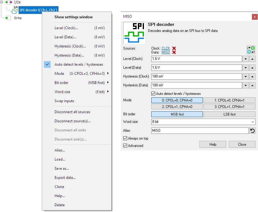
The SPI decoder always needs two sources: the first connected source will be used as SPI clock and the second connected source will be used as SPI data, either MOSI (data output from master) or MISO (data output from slave).
When both MOSI and MISO data need to be decoded, simply use two SPI decoder I/Os, connect the CLK signal to both I/Os, the MOSI data signal to one I/O and the MISO data signal to the other I/O.
The following fields are extracted from the SPI communication and shown as a column in a table:
| Field name | Purpose | Default shown |
|---|---|---|
| Value (Hex) | The value in hexadecimal notation | |
| Value (Dec) | The value in decimal notation | |
| Value (Bin) | The value in binary notation | |
| Value (ASCII) | The value in ASCII notation |
When decoding both MOSI and MISO data, connect both SPI decoder I/Os to the same table, after first setting its Layout to "Common rows".
Properties and actions
To control the behavior of the SPI decoder I/O, several properties are available.
These can be accessed through a popup menu which is shown when the I/O is right clicked in the Object screen.
The properties can also be accessed through its settings window which is shown when the I/O is double clicked in the Object screen.
To open the Object screen, click the  Show object screen button.

By default, the settings window only shows the most used settings. When Advanced is ticked, the extended window with all settings is shown. See also the program settings.
Swap inputs
The SPI decoder always needs two sources: the first connected source will be used as SPI clock and the second connected source will be used as SPI data. When the sources are connected the wrong way, the Swap inputs action will correct it.
Level (Clock) and Level (Data)
In order to decode the analog signals into a digital signal, the SPI decoder I/O compares the analog input signals with mid levels: anything above that level is considered "high" and anything below that level is considered "low". The Level (..) properties set a mid level for the Clock and Data signal individually.
Hysteresis (Clock) and Hysteresis (Data)
To minimize the effect of noise on the signals when comparing the signals to the mid levels, a Hysteresis can be used around these levels. Anything above "level + hysteresis/2" is considered "high" and anything below "level - hysteresis/2" is considered "low". The Hysteresis (..) properties set the size of the hysteresis for the Clock and Data signal individually.
Auto detect levels and hystereses
Enabling Auto detect level and hysteresis will let the software determine a suitable mid level and hysteresis, based on the measured signal. Each time new data is available, the suitable levels and hystereses will be determined again. In streaming mode, levels and hystereses are determined once based on the first chunk of data and remain at these values though out the whole measurement.
Auto detect levels and hystereses is default enabled.
Mode
The SPI decoder supports four SPI modes:
- Mode 0: Clock Polarity (CPOL) = 0, Clock Phase (CPHA) = 0
- Mode 1: Clock Polarity (CPOL) = 0, Clock Phase (CPHA) = 1
- Mode 2: Clock Polarity (CPOL) = 1, Clock Phase (CPHA) = 0
- Mode 3: Clock Polarity (CPOL) = 1, Clock Phase (CPHA) = 1
The Mode property determines which mode the SPI decoder uses. The default Mode setting is Mode 0.
Bit order
The bit order of transferred data on the SPI bus is not defined in a standard, it depends on the implementation. The Bit order property determines how the SPI decoder will interpret the decoded bits: MSB first or LSB first. The default Bit order is MSB first.
Word size
The word length of transferred data on the SPI bus is not defined in a standard, it depends on the implementation. The Word size property determines how many bits the SPI decoder will use for one word. Several predefined values are available and it is also possible to enter a user defined value. The default Word size is 8 bits.


