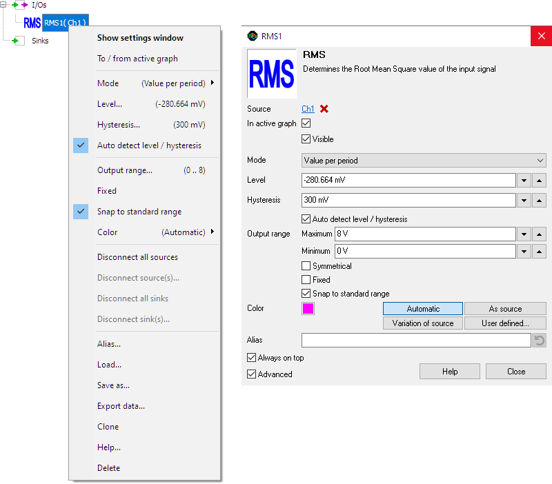
Depending on the selected mode, the RMS I/O returns one RMS value per period in the measured signal or one single value, which is the RMS value of the input signal.
A typical application of the RMS I/O is logging RMS values to monitor e.g. mains voltage.
Properties
To control the behavior of the RMS I/O, several properties are available.
These can be accessed through a popup menu which is shown when the I/O is right clicked in the Object screen.
The properties can also be accessed through its settings window which is shown when the I/O is double clicked in the Object screen.
To open the Object screen, click the  Show object screen button.

By default, the settings window only shows the most used settings. When Advanced is ticked, the extended window with all settings is shown. See also the program settings.
Mode
The Mode property determines how the RMS value is determined. Four modes can be selected from:
-
Single value for all data
The RMS I/O returns one single value, which is the RMS value of the total captured signal.
When analyzing streaming data, all data since starting the stream is being analyzed, resulting in one value for the total stream. -
Single value for trimmed data
The RMS I/O determines the RMS value over all complete periods found in the input signal and returns one single value for that whole section.
When analyzing streaming data, all data since starting the stream is being analyzed, resulting in one value for the total stream.
Incomplete periods at the start and the end of the record are trimmed away. -
Value per period
The RMS I/O locates each period in the signal and determines the RMS value for each complete period in the signal. The RMS I/O returns an RMS value for each period that is found.
Incomplete periods at the start and the end of the record are ignored. In streaming mode these are matched with the corresponding incomplete period of the next chunk and included in the result. -
Value per chunk
The RMS I/O returns one single value for the last received chunk of data.
When analyzing streaming data, each chunk produces one value, which can be collected in a Data Collector.
Level
In order to find the periods in the measured signal, the RMS I/O locates the rising slopes in the signal, around the mid level of the signal. This mid level can be set manually using Level.
Setting the level is only required when the Mode is set to Single value for trimmed data or Value per period.
Hysteresis
To determine whether a slope is rising or falling, a hysteresis is used. This hysteresis determines how much the signal, with respect to the Level, must become larger in order to detect an edge. With a larger hysteresis, the detection is less sensitive for e.g. noise on the signal. If the hysteresis is too large, edges might be missed. This hysteresis can be set manually using Hysteresis.
Setting the hysteresis is only required when the Mode is set to Single value for trimmed data or Value per period.
Auto detect level / hysteresis
When Auto detect level / hysteresis is enabled, the I/O tries to determine the the mid level and a suitable hysteresis automatically.
Setting the Auto detect level / hysteresis is only required when the Mode is set to Single value for trimmed data or Value per period.


