
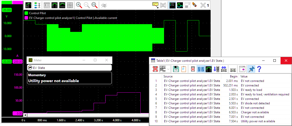
The Control Pilot signal is a square wave signal with a frequency of 1 kHz, both pulse width modulated and amplitude modulated. The pulse width modulation indicates the amount of current the EVSE can deliver for the charging process. The amplitude modulation indicates the status of the charging process.
To analyze the Control Pilot signal, the Control Pilot signal (CP) must be measured, relative to the vehicle ground (PE). It is recommended to do this using a scope with differential inputs. As the charging process is a long process, it is best to measure this in continuous streaming mode, with a streaming rate of 500 kSa/s or higher. In the software, the used input channel has to be connected to the EV Charger Control Pilot Analyzer I/O. A Quick Setup for analyzing the charging process is available in the Quick Setups, in the Automotive section.
The EV Charger Control Pilot Analyzer I/O has two outputs:
Available Current: indicating the maximum current that is available at the charging point. This is not the actual current flowing. This output provides a numerical value, that can be shown in a Meter display or a Graph.
State: The state of the charging point and EV, during the charging process. This output provides a text string, that can be viewed in a Meter display, set to the Text type and showing the Momentary value. Possible charging states are:
- EV not connected
- EV connected
- EV ready to load
- EV ready to load, ventilation required
- Utility power not available
- Charger not available
- EV diode not detected
- Undetermined
Properties and actions
To control the behavior of the EV Charger Control Pilot Analyzer I/O, several properties are available.
These can be accessed through a popup menu which is shown when the I/O is right clicked in the Object screen.
The properties can also be accessed through its settings window which is shown when the I/O is double clicked in the Object screen.
To open the Object screen, click the  Show object screen button.
The EV Charger Control Pilot Analyzer I/O and both outputs each have their own popup menu and settings window.
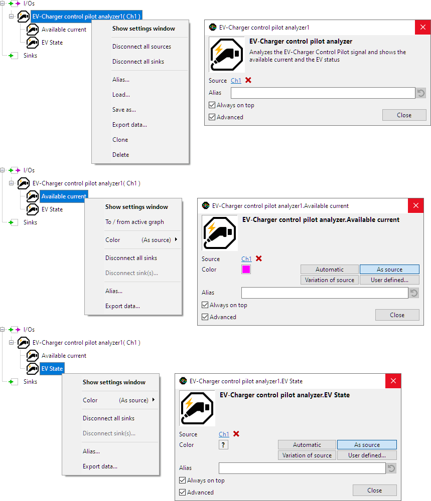
By default, the settings windows only show the most used settings. When Advanced is ticked, the extended window with all settings is shown. See also the program settings.
Common properties and actions
Related information

Crankshaft angle
The Crankshaft Angle I/O converts a crankshaft position sensor signal into a crankshaft angle signal.