Typical applications of the FFT I/O are to create a spectrum analyzer to examine the frequency response of a system or to examine the harmonic distortion in a system.
To convert the spectrum into a density spectrum, a Gain / Offset I/O can be connected after the FFT I/O. Enable its Spectrum to density setting to convert a magnitude spectrum into a density spectrum.
Properties
To control the behavior of the FFT I/O, several properties are available.
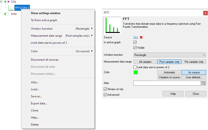
These can be accessed through a popup menu which is shown when the I/O is right clicked in the Object screen.
The properties can also be accessed through its settings window which is shown when the I/O is double clicked in the Object screen.
To open the Object screen, click the  Show object screen button.

By default, the settings window only shows the most used settings. When Advanced is ticked, the extended window with all settings is shown. See also the program settings.
Window
The Fast Fourier Transform treats the input signal as if it was a periodical signal. In other words, it assumes the signal is an infinitely long series of repetitions of the record. In practice, mostly the record does not contain an integer number of cycles of the signal. Therefore, if the end of the record is connected to the beginning, a discontinuity will arise, which results in extra frequency components in the resulting spectrum. This effect is called spectral leakage.
To minimize the effect of spectral leakage, the input record of the FFT can be multiplied with a Window. This is called windowing. Several windows can be chosen in the menu of the FFT I/O, which all basically perform the same action: they make the edges of the record smoother to make the discontinuities smaller. In most cases, the Blackman-Harris window will give the best results. However, if your data contains an integer number of cycles, the rectangle (no windowing) window will give the best result. The following window functions are available for the FFT-block:
- Rectangle
- Hanning
- Hamming
- Bartlett
- Parzen
- Welch
- Blackman
- Blackman-Harris
- Flat top
- Nuttall
- Blackman-Nuttall
Measurement data range
The data range over which the FFT is calculated can be set to one of the following settings:
- All samples: Use both pre samples and post samples to perform the FFT calculation.
- Post samples only: Use only the post samples to perform the FFT calculation. (Default)
- Pre samples only: Use only the pre samples to perform the FFT calculation.
Limit data size to powers of 2
The FFT I/O supports two algorithms to determine the frequency spectrum. One algorithm can use any amount of samples to calculate the spectrum. The other algorithm requires the number of samples to be a power of two: e.g. 512, 1024, 2048, etc.. The algorithm with the limitation on the amount of samples is faster, the other algorithm can determine a more accurate spectrum of the measured signal, as it can use all samples.
Enabling the setting Limit data size to powers of 2 will make the FFT I/O use the faster algorithm, where the largest possible "power of 2" amount of samples from the selected data range is used. When the setting is disabled, the full selected data range is used.
Common properties and actions
Limitations
Performing FFT operations on very large data sets can be time consuming and memory consuming. In certain situations it may not be possible to perform an FFT operation with the selected record length and pre trigger setting and the available RAM in the computer. In that case, the software will clip the used number of samples to the largest amount of samples that can be used for the FFT operation. All subsequent measurements with the same settings will use the same valid amount of samples for the FFT operation.
To avoid this situation use one or more of the following suggestions:
- set pre trigger to zero or set the FFT measurement data range to All samples.
- enable FFT Limit data size to powers of 2


