June 13, 2024
Version 1.47 of the Multi Channel oscilloscope software is now available for download.
A lot of changes have been made to add new functionality and to improve basic operations in the software. This is a categorized overview of some of the changes.
Contents
Phase cursors
When examining phase shift between signals, or examining other periodic signals like e.g. crankshaft signals, special Phase cursors can be switched on in the graph.
With these special cursors, the beginning and end of a cycle can be marked, which then is considered to be 0 to 360 degrees. It is also possible to mark that area as being 0 to 720 degrees, 0 to 100 % or some user defined range. The regular cursors can then be used to determine the angle of a specific position in the cycle. This angle is determined using linear interpolation between the two limits of the range.
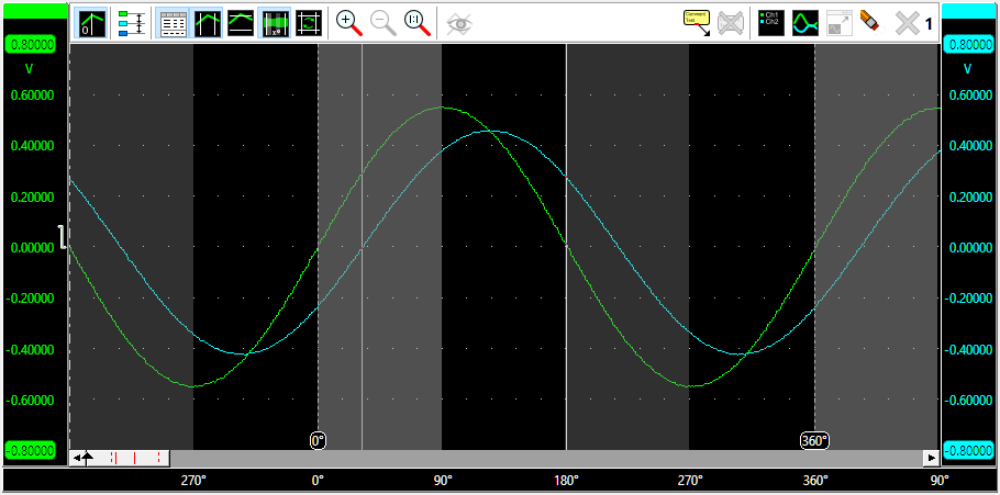
For automotive applications, the new Phase cursors are also very useful, in identifying the different strokes of an internal combustion engine. When used in combination with a Crankshaft angle I/O, the different strokes are clearly identified in the crankshaft signal.
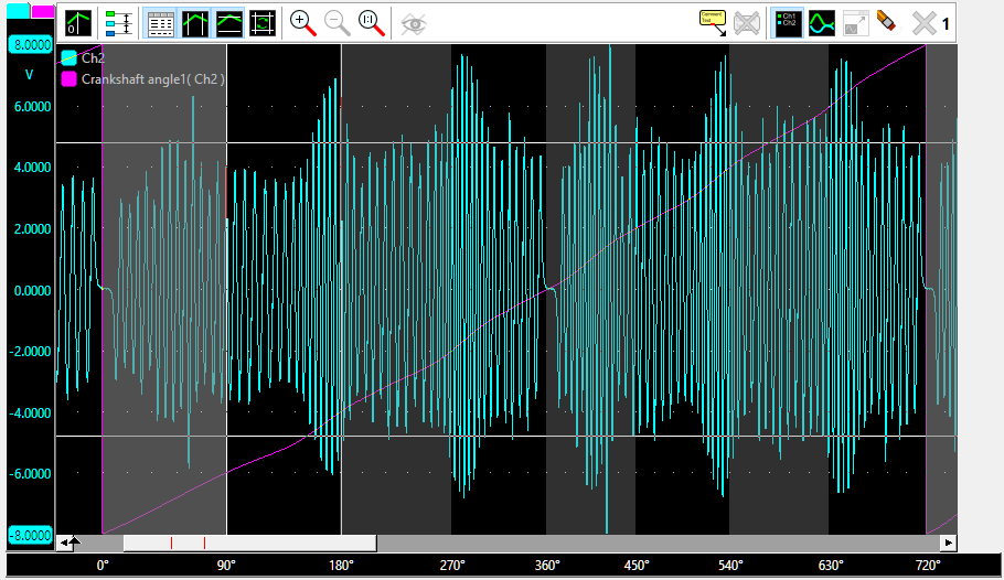
More information on the phase cursors and how to set them up can be found at the Graph page.
New EV Charger Control Pilot Analyzer I/O
The process of AC charging an Electrical Vehicle (EV) using a Type 2 coupling can be monitored by analyzing the information that is transferred by the Control Pilot (CP) signal. The EV Charger Control Pilot Analyzer I/O can be used to analyze this signal and show the available amount of current that can be provided by the charging point and the status of the charging process.
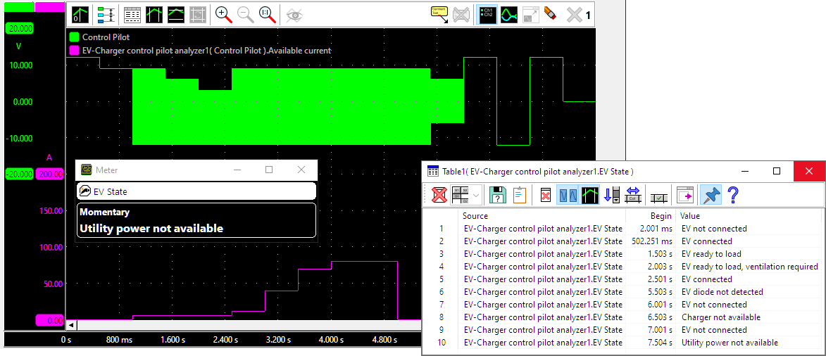
The available current can be shown in a graph and on a meter, the charging status can be shown on a meter and in a table.
More information can be found at the EV Charger Control Pilot Analyzer I/O page.
New Meter display options
Two new displaying options have been added to the Meter sink, displaying of non-numerical data and a single column display mode.
Besides a seven segment display and a gauge display, the meter displays can now also display alphanumerical data, like the charging status messages from the EV Charger Control Pilot Analyzer I/O.
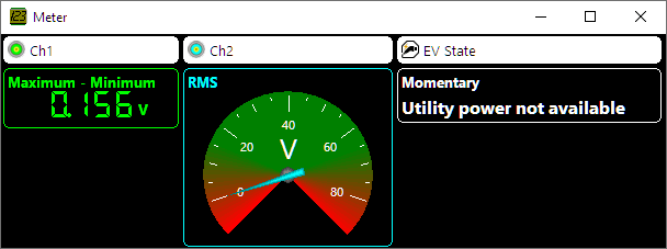
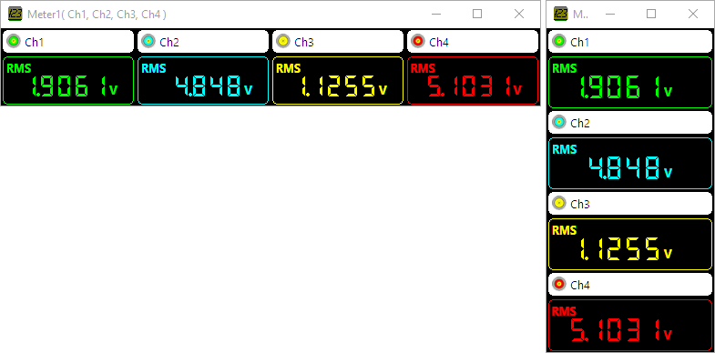
When measurements for multiple sources are displayed in the Meter sink, by default each source gets its own column with displays. When many sources are connected, the total Meter display can become very wide. In that case it can be more convenient to set the Meter to Single column, where all sources are shown in a single column, below each other.
Rearranging objects in the Object Tree
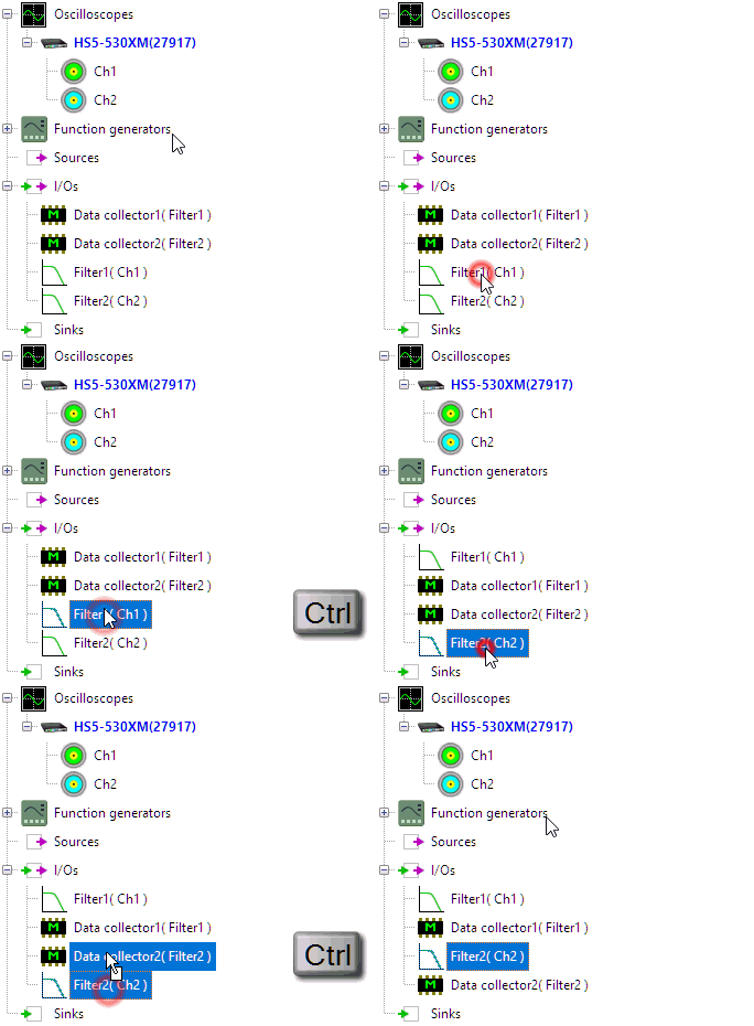
The order in which objects are listed in the Object Tree can be changed. This can be useful when e.g. the setup has been modified because objects were inserted or removed. The I/Os can then appear in an order which is not convenient. By dragging the objects with the Ctrl key pressed, a better ordering can be achieved.
For more information, see the Advanced measurements page.
Other changes
Several other improvements and additions are made to the software. The most important are:
-
Standard measurement
 Momentary added to the cursors and the Meter.
Momentary gives a momentary value of the measured signal, it is the last, or right-most value in the sample range.
- Added -console command line option to run the Multi Channel oscilloscope software without showing the user interface and closing after processing of other command line options. This option can be used e.g. when using Multi Channel oscilloscope software to export data or images from setfiles.
- Added In use by <name> in Manage instruments dialog status column for WiFiScopes.
- Added Clock synchronized indication for wirelessly combined instruments to instrument settings dialog.
-
Show peaks and harmonics
- Fixed incorrect drawing of peaks when using logarithmic horizontal axis.
- Fixed that the unit factor of the value was not drawn in the labels.
- Fixed layout of double field entry box used e.g. by axis Visible range.
