The Multi Channel oscilloscope software has a modular structure, with Sources, I/Os and Sinks.
Sources

Sinks

I/Os

Basic math
These I/Os perform a basic mathematical operation on one or more signals:
| I/O | Function |
|---|---|
 Gain / Offset Gain / Offset |
Apply gain and/or offset to a signal |
 Add / Subtract Add / Subtract |
Add or subtract up to 32 signals |
 Multiply / Divide Multiply / Divide |
Multiply or divide up to 32 signals |
 SQRT SQRT |
Calculate the square root of a signal |
 ABS ABS |
Determine the absolute value of a signal |
 Differentiate Differentiate |
Differentiate a signal |
 Integrate Integrate |
Integrate a signal |
 Log Log |
Calculate the logarithm of a signal |
Filtering I/Os
These I/Os perform a filtering operation on a signal or consecutive signals:
| I/O | Function |
|---|---|
 Filter Filter |
Fully configurable filter |
 Ideal Filter Ideal Filter |
Fully configurable Ideal filter |
 Signal cleaner Signal cleaner |
Remove noise and other distortions from periodical signals |
 Average Average |
Outputs the average of n measurements |
Adjusting I/Os
These I/Os perform an adjusting operation on a signal or consecutive signals:
| I/O | Function |
|---|---|
 Deskew Deskew |
Shift the input signal horizontally, in time |
 Slice Slice |
Ouputs a selectable slice of its input signal. |
 Limiter Limiter |
Clip the input signal between a minimum and maximum limit |
 Comparator Comparator |
Compare the input signal with a selectable reference level |
 Resampler Resampler |
Changes record length and sampling frequency of an input |
 Window Window |
Applies a window function to its input signal |
Miscellaneous I/Os
These I/Os perform an other operation on a signal or consecutive signals:
| I/O | Function |
|---|---|
 Min / Max detector Min / Max detector |
Peak detection with optional fall-off |
 Data collector Data collector |
Appends small chunks of data to one big record |
 Reference Reference |
Holds a copy of a signal |
Analyzing I/Os
These I/Os analyze the input data and extract specific information from it.
| I/O | Function |
|---|---|
 Duty cycle Duty cycle |
Determines duty cycle percentage |
 RMS RMS |
Determines RMS value(s) of the input signal |
 Maximum Maximum |
Determines Maximum value(s) of the input signal |
 Maximum-Minimum Maximum-Minimum |
Determines Maximum - Minimum value(s) of the input signal |
 Minimum Minimum |
Determines Minimum value(s) of the input signal |
 PhaseDifference PhaseDifference |
Determines phase difference between two input signals |
 FFT FFT |
Perform a Fast Fourier Transform (Spectrum analyzer) |
 PSD PSD |
Determine the Power Spectral Density of a signal (Spectrum analyzer) |
 EMI EMI |
Creates an environment that can be used for EMI pre-compliance testing. |
 Histogram Histogram |
Determine the Histogram of a signal |
Automotive I/Os
These I/Os perform automotive specific operations on the data.
| I/O | Function |
|---|---|
 RPM RPM |
Converts a crankshaft sensor signal into Revolutions Per Minute |
 Crankshaft angle Crankshaft angle |
Converts a crankshaft sensor signal into the crankshaft angle |
 EV Charger Control Pilot Analyzer EV Charger Control Pilot Analyzer |
Decodes the Control Pilot signal and shows the maximum available charge current and the charge status |
Decoding I/Os
These I/Os decode serial communication data from the input data and present the decoded messages.
| I/O | Function |
|---|---|
 Pulse decoder Pulse decoder |
Decodes the A and B signal from a quadrature encoder to position |
 I2C decoder I2C decoder |
Decodes analog data on an I2C bus to I2C data. |
 UART / Serial Decoder UART / Serial Decoder |
Decodes analog data on a serial bus (UART, RS232, RS458, Midi, DMX, LIN) to serial data. |
 CAN decoder CAN decoder |
Decodes data on a CAN bus |
 J1939 decoder J1939 decoder |
Extracts SAE J1939 SPN values from CAN messages |
 SPI decoder SPI decoder |
Decodes data on a SPI bus |
Using sources, sinks and I/Os
All measurement setups in the Multi Channel oscilloscope software are built from one or more sources, I/Os and sinks. These are simply connected to each other by dragging and dropping. Multiple I/Os can be used to form complex mathematical operations.
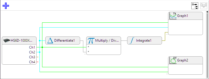
In the image above, three I/Os are used to determine the area that is enclosed by two signals in XY mode.